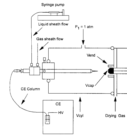
Coaxial Sheath Solvent Ion Spray Interface - 3
An important contribution to development of the coaxial sheath solvent ion spray interface came from Banks. All the designs described before applied the electrospray voltage to the spray needle and are grounded through the spray with the mass spectrometer entrance. Banks noted that this approach has two essential disadvantages22,23.
- The CE column exit must be floated at the required ES potential (several kV) causing the resulting electric field applied to the CE capillary to be the difference between the applied CE voltage and the ES voltages.
- If the ES voltage is applied during the injection phase, the sample constituents loaded on the capillary will tend to migrate back out of the capillary entrance by a reverse EOF that is generated by the ES voltage.
In addition in this configuration, the CE voltage is also grounded at the MS entrance and driving a current of several µA into a circuit designed to handle nA. An additional high ohmic resistor chain must be to overcome this problem.
Banks concluded that CE-ESI/MS interfacing is complicated by the need to complete electrical paths for both the CE and the ESI current. The ideal arrangement to accomplish these requirements is to maintain the CE column exit at ground potential so that the electric field applied across the CE column is referenced to 0 volts on the outlet, as is normally the case for CE.
In addition, Bank proposed the usage of a translation device that would allow the positioning of the end of the CE capillary precisely and reproducible in front of the MS entrance.
Though there is not too much detail in the drawing from reference 22, conceptually it contains all the characteristics of the triple tube sheath solvent flow interface for CE-MS that was brought to the market by Hewlett-Packard in 1995.
Aspects of this IF will be the theme in a separate blog on CE-MS on this website.
![]()
22J. Fred Banks Jr., J. Chrom., 712, 245 (1995)
23J.Fred Banks Jr., Electrophoresis, 18, 2255 (1997)
