Initial Work to Interface CE with a mass spectrometer
Several approaches to couple CE with MS were reported in the late eighties. These can be divided into three different approaches:
- direct spray with metal or metalized needle for electrical contact
- liquid junction interface where the BGE in the capillary is hydraulically connected to a reservoir where electrical contact is present
- co-axial sheath flow interface where a conductive solvent flows around the outside of the CE capillary and provides a hydraulic connection to an electrical contact
Smith8 , Banks9 , Vouros10, Chen and Maxwell11 have described the early developments of CE-MS in comprehensive reviews.

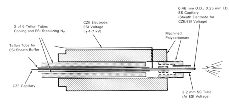
Schematic illustration of the CZE-MS interface using a liquid sheath electrode
After two futile attempts to use a metal sheath capillary with the silver coated CE capillary exit for direct electrospray12,13,, Smith an coworkers of Pacific Northwest Laboratory reported the use of a solvent as a sheath around the CE separation capillary end to provide a wet, electrical contact on the outlet side14,,15,. They used a 1.6 mm o.d. Teflon tube to hold the CE capillary (0.2 mm o.d.x 0.1 mm i.d.).
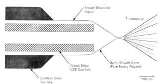
Via a T-piece the Teflon tube was connected to a syringe pump which delivered the sheath solvent at flow rates of 5-10 µL/min. A metal needle 0.46 mm o.d. and 0.25 mm i.d. was sealed into the Teflon tube and was connected to the electrode providing the electrospray voltage. Towards its end, the CE capillary protruded through a metal needle and extended about 0.2 mm. In addition, nitrogen gas was delivered with a gas flow rate of 0.1 - 1 L/min through an SST capillary of 0.5 mm i.d. intended to shield and cool the spray. The parts were fixed in a polycarbonate device. In the figure below a schematic view of the spraying, a tip is given. The shield gas is not shown in this picture.

ESI interface tip showing the liquid sheath electrode
Smith clearly states that without the sheath solvent it was impossible to obtain a stable electrospray from the electro-osmotic flow only. Thus, besides providing the electrical contact between the separation capillary and the ESI needle, the sheath solvent also delivers the bulk of the liquid for the electrospray process. The flow of a shielding gas was intended to cool and/or protect the spray from discharging (e.g. with SF6) but not required for forming the spray. With this approach the electrospray process became practically feasible.
The sheath liquid is the outlet buffer for the CE and maintains a spray independent of the magnitude of the EOF. Moreover, the sheath solvent can be chosen to provide optimal conditions for electrospray (low viscosity, low aqueous content) and can drive the ionization of the analytes to more favorable, in most cases low pH. In practice, most CE-MS separations are performed with BGE containing volatile buffers like ammonium acetate with a sheath solvent water with methanol or acetonitrile containing 0.1-1.0% acetic or formic acid.
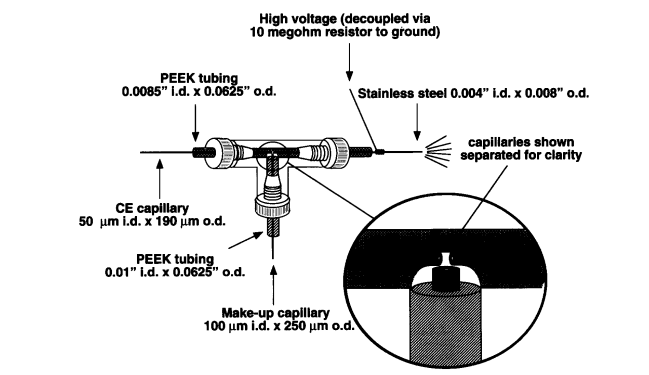
Nevertheless, this approach required engineering skills to construct such interfaces which inhibited the broad availability of this coaxial sheath flow interface. Moreover, since the electrospray voltage is applied to the end of the CE capillary continuously, the field in the CE capillary is affected and the end of the CE capillary must be connected to a resistor chain to avoid the CE current flowing toward the ground electrode at the MS inlet. An example is shown in the figure below from later work by Henion et al. The high voltage required for electrospray is grounded via a megohm resistor to ground 16 .

![]()
8R. D. Smith et al., Anal. Chem., 65, 574A (1992)
9J.F. Banks, Electrophoresis, 18, 2255 (1997)
10P. Vouros et al., Anal. Chem., 71, 378A (1999)
11E.J Maxwell, D. D.Y. Chen, Anal. Chim. Acta, 627, 25 (2008)
12R. D. Smith et al, Anal. Chem. 60, 436, (1988)
13J.A. Olivares, N.T. Nguyen, C.R. Yonker, R.D. Smith, Anal. Chem., 59, 1230 (1987)
14R.D. Smith, C.J. Barinaga, H.R. Udseth, Anal. Chem., 60, 1948 (1988)
15R.D. Smith, H.R. Udseth, Nature, 331, 639 (1988).
16T. Wachs, R.L. Sheppard,J. Henion, J. Chrom. B, 685, 335 (1996).
