The 41th Symposium on High Performance Liquid Phase Separations and Related Techniques, HPLC2014, took place in the Hilton Riverside Hotel, New Orleansand from May 11-15. The symposium was attended by approx. 770 delegates. About 60-70 of these were registered as exhibitors. Accounting for invited delegates, there were about 600 paying delegates. More than 200 orals and over 450 posters were presented. Ca. 45 manufacturers exhibited besides 20 media partner. These numbers are significantly lower than at HPLC2013 in Amsterdam.
The orals were presented in three parallel sessions (for details check the symposium website). There were plenary sessions at the opening and closing day. Only registered delegates could attend the oral presentations. Free tutorials on global topics were presented by experts in the field and offered in parallel with daily oral sessions. In addition free lunch seminars instrument vendors offered information on their new products, services and new software.
Posters presentation and vendor exhibition took place jointly on the ground level of the hotel. Sundays welcome reception, vendor reception on Tuesday and boot tour on the Mississippi with the Steamboat Natchez completed the program.
Overall this issue of the HPLC symposium series was a disappointment compared with last year’s issue in Amsterdam. E.g. where these kind hotels in USA seldom offer good conference facilities (visibility, very noisy air-conditioning) the organizers seemed not to have been highly committed to offset such disadvantages themselves. One could not observe a true drive to make this HPLC symposium an exciting and memorable event (e.g. Sunday evening welcome reception was so modest that people left early to get some dinner on their own). Many practical matters were not well organized. One can easily speculated that the low attendance constrained the organizers in spending. But the low attendance may have been caused by the very late start of the promotion for the conference. One has to keep in mind that people need approval to attend a conference and travel which in industrial companies, in academia and in public organizations may take quite some time. It will be a challenge for the organizers of Geneva 2015 to annihilate these impressions and create an exciting event.
Following are a number of my personal impressions and notes which certainly are not delivering a complete picture on the conference. A detailed report on this symposium is published by Ron Majors in LC.GC Magazin. A private copy of this article can be taken here.
Uwe D. Neue Award Symposium.
Obviously, for me the highlight of the symposium was the receipt of the Uwe D. Neue Award in Separation Science sponsored by Waters Inc. The session was chaired by Martin Gilar of Waters who gave a brief account on Uwe Neue and the selection process (a PDF copy can be found on this page).
Prior to my talk on "Current and future Perspectives on UHPLC; Requirements for improved Abilities and Functionality" with my coauthors Dwight Stoll, Monika Dittmann and Konstantin Choikhet I gave a brief acceptance talk and thank you to many who allowed me to become awarded. You will find a PDF-copy of my talk at my website under "Publications" (access to this menu after login). I was followed by George Guiochon who talked about The Theory of Gradient Elution in Fast Reversed-Phase Liquid Chromatography. It was quite a revealing paper since it is easily forgotten that the organic modified in a gradient run itself is retained so that the gradient composition change may not be linear at all especially with fast gradients. Next Attila Felinger spoke about "The Appraisal of Inverse Size Exclusion Chromatography". Overall it was an exciting session for me and I was much more nervous than usual. Monika Dittmann registered part of the session on video which I will make available soon. Till then you will find a nice picture of Martin Gilar, last year’s awardee Jack Kirkland and myself.

Awardees together; from left to right, Martin Gilar, Jack Kirkland and Gerard Rozing
Following are short discussions of presented work that I think were very interesting and deserve a closer look.
Slip Flow Chromatography
The group of Mary Wirth at Purdue University recently published remarkable results that have drawn a lot of attention. In a nutshell:
- They demonstrated that they could work with columns that are packed with very small particles (< 0.5 μm) without suffering from excessive high back pressure
- They obtained ultra low values of HETP with such columns.
They have attributed the very low resistance to flow to a phenomenum called "slip flow" and therefore coined the term "Slip Flow Chromatography".
What is "slip flow"? In fluid dynamics it is assumed that at a solid boundary, the fluid will have zero velocity relative to the boundary. Based on this assumption, for a fluid flowing in a cylindrical tube one arrives at the Hagen-Poiseuille equation which describes the pressure over tube in dependence of the solvent viscosity η, average solvent velocity u, the length of the capillary and the capillary diameter.

In order to describe the resistance to flow through a packed bed, the Darcy equation is used (equation 2). It is similar to the Hagen-Poiseuille equation but with 8/r2 replaced by a proportionality factor which is called the permeability of the packed bed (I have described this and following details in my blog the permeability equations in this web; click here and following pages).
In the Kozeny-Carman equation the permeability of the packed bed is related to the packing density, particle size and particle morphology by assuming that the average space between the particles in the bed can be approximated by a bundle of very narrow capillaries. As a rule of thumb, this space can be also approximated as 1/3 of the particle radius.
The Kozeny-Carman equation bears a number of assumptions on the interparticle pore structure but still the so-called "no-slip"-condition is used. I.e. the velocity of the flow at the surface of the hypothetical capillary is zero.
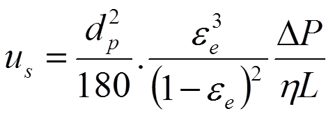
The Kozeny-Carman equation bears a number of assumptions on the interparticle pore structure but still the so-called "no-slip"-condition hold. The flow at the surface of the hypothetical capillary is zero.
Under "Slip Flow" conditions this assumption is abandonned and flow at the surface takes place.
In J. Am. Chem. Soc. 2012, 134, 10780 − 10782, Wirth visualized the slip flow as follows in figure 1. Though this may be a naive representation, it illustrates a smaller flow velocity profile which eventually may lead to a lower eddy dispersion term in the van Deemter equation and therefore lower HETP.
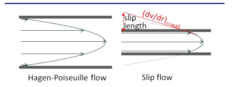
As argued in the reference mentioned before by Wirth, slip flow arises from weak intermolecular interactions between a fluid and the surrounding walls, e.g. giving significantly enhanced volume flow rates of water through hydrophobic channels, such as carbon nanotubes, nanopipes, and nanoscale carbon sheets (for references see the Wirth paper). I.e. one must conclude that the amount of slip flow that is obtained, strongly depends on the surface properties of particles in the bed or conduits. Another essential observation is, that slip flow occurs when the interparticle space or the conduit diameter is in the nanometer scale range.
The Wirth group packed 0.47 µm colloidal silica particles in a 75 µm fused silica capillary (Anal. Chem., 2010, 82, 2175). After packing, the particles were derivatized with C4 and C1 chlorosilanes. As given above the average space between these particles will be around 60 nm. The interparticle porosity measured by two different methods and was 0.28 which results in a column resistance factor according to the Kozeny-Carman equation at 4250.

Next the Wirth group measured the flow rate obtain in dependence of the applied pressure for a number of different solvents (figure 2). In order to account for viscosity differences the Darcy equation was plotted as (equation 3):
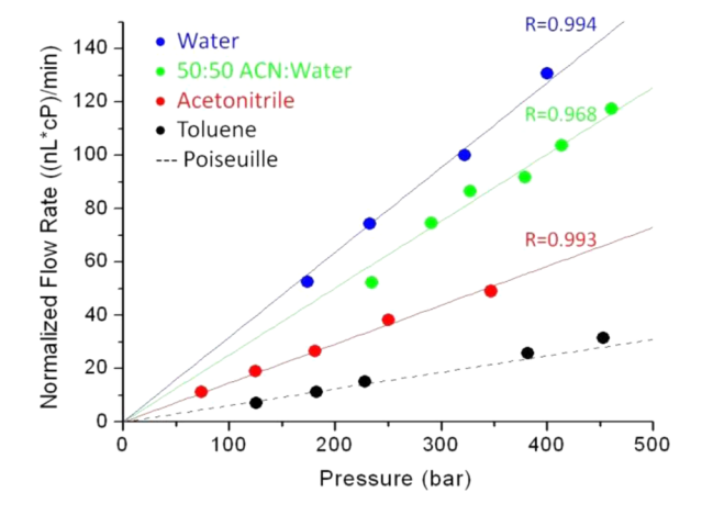
From this plot it can be concluded that the permeability of the column increases from toluene to water. This is remarkable indeed since the permeability is a physical geometric parameter of the packed bed and not dependent on the solvent that is pumped through the bed. The permeability calculated from the plot data for water is 2.62x10⁻¹⁰ mm2. Normalizing permeability on the particle size (0.47 µm) results in a column resistance factor of 843. This is remarkable since taking the Kozeny-Carman equation and substituting the value for the interstitial porosity found of 0.28 results in a column resistance factor of 4250. Given though the claim in the Wirth paper that the slip flow enhancement for water is a factor 5x over toluene, this would indeed result in a 5x higher value of the column resistance factor of the column for toluene.
So one can conclude that these data are consistent. Question remains to the why the resistance to flow is so much lower when the wettability of the particles is worst. Resp. the molecular reasons need to be understood. In a recent paper (Physical Review Letters, 96, 066001 (2006) Choi and Kim describe the occurrence of slip flow in nanoengineered conduits with very hydrophobic surfaces (thank you Monika for this reference). The surface structure they described didnot allow a liquid to contact the hydrophobic conduit service which led to very high slip flow. In addition, it seems to me that one cannot propagate the laws of physics for the macro or even micro world to the nano world. The volume/surface ratio of the spaces is getting so low that surface forces will dominate and may bear another explanation for the observed high permeability.
Regarding the claimed ultra low HETP values the situation is less clear since the measurement of the profile of ultra small bands is a challenge.
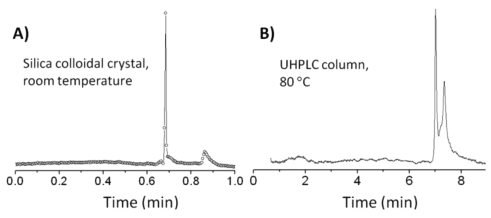
An example is shown in figure 3 with the separation of monoclonal antibody and aggregate (10782).
Overall, slip flow chromatography is an interesting pathway to achieve high efficiency separations but definitively needs more study to reveals the basics which will help to understand and optimize separations.
Further reading: in addition to the reference given check ACS Nano 7, 725–731 (2013) and Anal. Chem. 2013, 85, 6820 − 6825.
MicroChip Electrophoresis (MCE)
The Ramsey group (J. Michael Ramsey and Scott Mellors) presented their recent work on MicroChip Electrophoresis. Initial work by this group was published in Analytical Chemistry, 80, 6881 (2008). The principle layout of their chip is shown in figure 4.
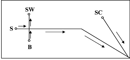
The chip is prepared from 150-µm thick Corning 0211 borosilicate glass. The channels that were obtained were about 75 µm wide and 10 µm high. The length of the separation channel S was 4.7 cm. They also described a 20.5 cm serpentine channel. The side channel was 2 cm length. The side channel is intended to deliver an EOF driven sheath solvent and connected to the separation channel 200 µm befor the tip.
In this initial work, the separation channel was coated with a cationic polymer (Poly E223, synthesized as described by Ulsten et al., Electrophoresis 2004, 25, 2090). This renders the surface of the channel positively charged and gave a good anodic EOF. Also in this way, adsorption of peptides and proteins with low pH BGE was suppressed. The side channel was not coated and delivers a small cathodic EOF. In this way, the flow direction in both channels is the same. To run the chip 1 kV was applied to SW and 4kV to SC (in case the long channel was used, negative voltages were applied to B, S and SW and 4.5 kV to SC. Given that the mass spectrometer inlet was at ground (Micromass Q-ToF) the circuit is closed. Background electrolyte was 0.2% acetic acid in M/W 1:1. Peptides, proteins and a BSA digest were used as samples.
This initial work showed feasability with moderate sensitivity though (1 µM in sample concentration). In the work presented at the symposium, the group explained to use chemical vapour deposition to coat the separation channel since the cationic polymer was found to coat inhomogeneously on the surface leading to broadening due to Taylor dispersion andpoor peak shape. This work was published recently in Anal. Chem. 2014, 86, 3493. Aminopropyl triethoxy silane was used in the CVD process. Significant improvement of efficiency and excellent long term stability as a consequence by the very homogenous coating of the separation channel S was reported.
While at the conference, Dr. Ramsey introduced me to Dr. Kevin J. Knopp who is the President and CEO of 908devices. This start-up company based in Boston, of which Mike is one of the founders, focusses on portable, high pressure mass spectrometers and their application in on-site the analysis of chemical warfare, toxic industrial chemicals, explosives, drug-of-abuse and environmental problems. I recommend to review the website. It seems a very promising pathway to practical application of a µTAS system.
CE-MS Interfacing
This is a hot area in the field. After being a promise for almost 4 years Beckman-Coulter, now a part of Sciex and called Sciex Separations, re-introduced the sheathless flow CE-MS interface according to Moini to the market. See the brochure on the company's website. On the other hand, the Agilent triple tube sprayer approach towards CE-MS is on the market for almost 20 years as a commercial customer solution. I do not intend to provide a relative assessment of both approaches here, but spend some detail on the Dovichi approach for CE-MS interfacing which he presented at the conference. It needs to be mentioned, that besides these three CE-MS IF methods, the Chen group in Vancouver and the Smith group in Seattle also have come up with new, sheathless solvent IF methods for CE-MS. I have been invited to contribute to a review article on CE-MS in Chromatographia special issue called "Recent Developments in Clinical Omics" where I will address these new developments.
In Rapid Commun. Mass Spectrom. 2010; 24: 2554–2560 Dovichi's interface is described. More details of his approach are revealed in Angew. Chem. 2013, 125, 13906 and in Proteomics 2014, 14, 622 (figure 5).
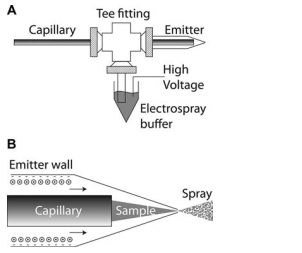
A. Electrokinetically-pumped sheath-flow nanoelectro-spray interface.
The separation capillary is threaded through a plastic union into a borosilicate glass emitter. Plastic tubing is connected to a side arm and an electrospray buffer. High voltage is applied to that buffer to drive an EOF that generates the electrospray. The separation is driven by the difference in voltage applied to the two ends of the capillary.
B. Detail of the emitter.
Anionic sites on the emitter wall attract cations that form an electrical double layer. The electrospray potential drives these cations to the emitter tip; the cations drag buffer with them, creating electroosmotic flow. This electroosmotic flow ensheaths the sample stream as it exits the separation capillary. Electrospray is generated as the solution exits.
The CE capillary is typically 150 µm o.d. and 50 µm i.d. The orifice is 2-10 µm and the distance between the distal end of the capillary and the orifice should be less than 1 mm. Separation buffer used ammonium acetate at pH 5.5. The sheath solvent aqueous methanol with 0.2% acetic acid keeping it about the iso-electric point (?) of the borosilicate glass. The voltage to drive the sheath solvent is 300 V/cm.
The voltage connected to the sheath solvent buffer serves two purposes; to provide the electrospray voltage and to generate some EOF
In an electrical sense, this seems a questionable approach. There are two DC powersupplies on the circuit with ground connection on the MS spectrometer. The CE current with the BGE used, will be in the order of a few µA and is delivered to the MS. Allthough it is claimed that the spray is formed by EOF generated by the borosilicate sprayer needle the reason for having a the sheath flow becomes not clear from the manscripts. Why borosilicate glass? Any EOF at that pH of the sheath solvent will be very low. Also borosilicate glass is much more fragile then fused silica which has the same pKa for the surface silanols. Certainly one must be concerned about alignment of the two capillaries.
Any way, Dovichi reports excellent sensitivity (sub fmol). Given the usage of 25 µm separation capillaries and assuming a few nL injection, the sample concentration would be in the 50-100 nM range.
At the conference Dovichi reported the usage of a dynamic pH junction to preconcentrate digested protein samples at 0.01 mg/ml level. In this case 50 µm i.d. separation capillary was used. This approach resulted in two benefits. First the peaks obtained are narrower leading to a higher number of identified peptides. Sample injection up to 0.5 µL was possible without deterioration of the peaks and therefore better sensitivity.
Best Poster Award at HPLC2014
Unlike many years before, the organizers of the meeting asked Monika Dittmann and Chris Pohl to arrange the poster review for the Best Poster Award. SInce there were much less poster compared with 2013 so there was less work for the reviewers to do giving them more time with the authors. Monika has kindly joined her award presentation with me which you can finde in the menu item "Reprints from others" (you must have an account to access this menu).
Some authors have shared their posters with me which you can find in the same menu.
